Assembly/Outfeed Table
Welcome to my Assembly Outfeed Table build article! I hope you’re excited!
If you’re not excited, maybe curiosity alone will keep you around.
Aaaaanyway, on to the reason we’ve gathered here today…assembly and outfeed tables!
Outfeed Tables
An outfeed table is simply just a flat surface that catches the material after making the cut on your table saw (or really any tool that feeds stock from one end to another). Jointers, planers, etc all have (or can have) outfeed tables. From the day I first got my table saw I have wanted an outfeed table. Cutting anything over, say, two feet was anywhere from annoying to dangerous. Like many of us, I used a roller stand at first. That’s fine for narrow stock but when you start getting wider than 18 inches or so it can get pretty cumbersome. Especially trying to juggle the offcut.
The Benefits of an Outfeed Table

Roller Stand (Poor Outfeed Table)
Having an outfeed table serves multiple purposes. First, it’s a time saver. No tracking down the roller stand. No start and stops as you go around the saw to pick up the numerous pieces of stock that fall off the stand or don’t make it to the stand because you didn’t put it close enough to the saw. Secondly, and most importantly in my opinion, is the safety aspect.
A Real Life Case for an Outfeed Table
My first project after getting my table saw was some window boxes. The majority of each box was made up of Azek (PVC) trim. Much like PVC pipe, Azek is really flimsy along its length. I was ripping a lot of 4 and 6 inch pieces that were 8 feet long. I messed up a few times getting the roller stand in the right position and handling the stock late in the cut got a little dicey. One time the stand was too high because the Azek had sagged so much that I ran the stock right into the stand and had to push the stand over to continue the cut. Having an outfeed table takes all of that worry and danger away.
Just Do It
It took me months before I finally decided to build an outfeed table. I let my “I really want to get this right” approach derail me many times. The truth is, an outfeed table can be something as simple as a sheet of plywood on a couple of saw horses or 2×4 legs. If you don’t have an outfeed table I highly recommend rigging up even the most rudimentary one you can fashion.
Assembly Tables
My first assembly table. It was crap.
An assembly table is really nothing more than a surface where you can assemble projects. Some people say that an assembly table is dead flat, but that’s just not the case. Lots of assembly tables aren’t remotely flat but they get the job done (to some degree). Ideally, an assembly table will be flat. My first assembly table was a severely warped piece of plywood stretched across a couple of sawhorses. Got the job done, but it was frustrating to say the least and not at all stable. With that said, the plywood/sawhorse combo can definitely be flat and usable. A lot of people use old doors for their surface which is a good, economical choice.
The Possibilities Are Endless
Like just about everything else in this hobby/trade/career, the quality, complexity and features of assembly tables stretch across a vast spectrum of possibilities. The aforementioned plywood/sawhorse combo on one end, and something like a Festool MFT on the other. This article will cover something closer to the former.
Saving Some Space with an Assembly Outfeed Table
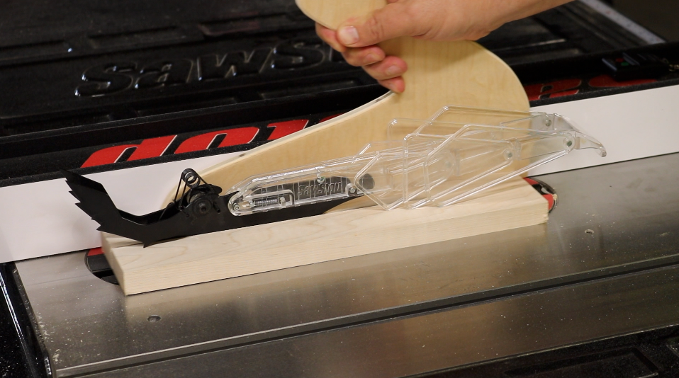
Many of us, especially on the hobby side of things, work out of pretty small shops. Quite often just a one or two car garage. With that being the case for me, I wanted to try and kill two birds with one project by making my assembly and outfeed one in the same. There’s only two considerations for making your assembly table double as your outfeed table. The first is height. Make sure it’s at or below (just a smidge) your table saw. The other is making allowances for your miter gauge or crosscut sled. We’ll need to cut out some of the top to address that issue.
Special Consideration for Contractor Saws
One of the big differences between contractor saws and cabinet saws is that contractor saws have the motor hanging off of the back of the saw. This creates a problem if we want to push our table right up against the saw as the motor will get in the way. Also, depending on how thick your table top is, the motor might come into contact with it when tilted to 45 degrees. I have addressed both of these issues (for my saw, at least, which is a SawStop contractor saw) in the design of my assembly/outfeed table.
The Design
When it came time to design my table there were a few other criteria I wanted to to adhere to in addition to what has already been mentioned:
- I want it pretty stout. Since I dont have a big, sturdy workbench I want my assembly table to be pretty heavy and not rack. To achieve this I simply used more materials than were probably necessary.
- It’s gotta be mobile. Depending on the task at hand I move my table around often. Since this won’t be a light table I will be putting casters on it and since I dont want it racking those casters will be the lifting type. Rockler bench casters are a great solution.
- Small footprint. As mentioned before, space is a premium in my shop and I often move things around so I can get my car in the garage if I am going to be away for a while or if there is a storm brewing. To compensate for the motor the table top will overhang the frame by about a foot so I decided to make that overhang foldable which saves about 1/4 of the footprint.
- Lastly, I want it to look decent so I dressed up the sides of the top with some hardwood and contrasting dowels to fill in the screw holes.
Materials & Tools
Lumber and Sheet Goods
- 2 – 4’x8′ sheets of 3/4″ MDF – https://tinyurl.com/yavs2qw6
- 1 – 1/8″ sheet of hardboard – https://tinyurl.com/y7c2vpj7
- 3 – 8′ 2x6s – https://tinyurl.com/y7fn8cw6
- 6 – 8′ 2x4s – https://tinyurl.com/y9wa8dzl
- 3 – 1×4 hardwood (I used maple. You can use anything you have on hand. If you are able to mill your own wood you dont need to get dimensioned lumber. I do not so I relied on what I was able to get at my local big box home center.) – https://tinyurl.com/y9due5u2
- 1 – 1/4″ dowel (I used walnut) – https://amzn.to/2W9q530
- 1 – 4’x8′ sheet of plywood (You only need about 60″ x 30″ worth of material here so check your scraps. You could get away with as thin as 1/4″ as this is just for the bottom shelf.) – https://tinyurl.com/yajafghg
Hardware & Fasteners
- 4 Pack Workbench Casters – https://amzn.to/3gIKup7
- 4 – 4 Pack Levelers – https://amzn.to/37SM9V2
- 1 – 48″ piano hinge (Any hinges will work. A piano hinge seemed easiest.) – http://amzn.to/2FdLdf5
- 4 – 3/8″* x 20 x 3″ hex bolts – https://amzn.to/3oMgSKh
- 4 – 3/8″* x 20 nuts – https://amzn.to/3mnBCGZ
- 8 – 3/8″* washers – https://amzn.to/3p0LAjh
- ~2 – 1 lb box 3″ deck screws – http://amzn.to/2m6BX3z
- ~1 – 1 lb box #6 x 1 1/4″ screws – http://amzn.to/2m3pDkA
- 16 – #6 x 2″ screws – http://amzn.to/2COKthW
- 1 – Box #6 x 3/4″ countersink sheet metal screws – http://amzn.to/2CBz6qr
- 1 – box #10 x 3/4″ sheet metal screws – http://amzn.to/2CCELfQ
- ~1 – 1 Gallon Bottle of Wood Glue – http://amzn.to/2CNYlsQ
*I used 3/8″ because I had some lying around. You could easily get away with 1/4″ or 5/16″.
Tools I will be using in this build
- Circular Saw – https://amzn.to/3gJX1Zu
- Flush Trim Saw – https://amzn.to/3gKxnnx
- Drill and Impact Driver – https://amzn.to/3qQk75j
- Bosch Router – https://amzn.to/2WdzoyZ
- Ridgid Trim Router – https://amzn.to/34byYgW
- WEN 10″ Bandsaw – https://amzn.to/3qUilQz
- WEN 12″ Drill Press – https://amzn.to/347Yynh
- Contractor Table saw – https://amzn.to/3nb0K4K
- WEN 4″ x 36″ Belt/Disc sander – https://amzn.to/3nfT0yh
- WEN Oscillating Spindle Sander – https://amzn.to/3qUr19S
- Dewalt Random Orbital Sander – https://amzn.to/3491uA6
- Craftsman 10″ Miter saw – https://amzn.to/37eKYjW
theaveragecraftsman.com is a participant in the Amazon Services LLC Associates Program, an affiliate advertising program designed to provide a means for sites to earn advertising fees by advertising and linking to amazon.com
Let’s Start Building the Assembly Outfeed Table
Cutting All of the Base Parts to Size
The first thing we’re going to do is break down all of these 2x4s and 2x6s at the miter saw. When we’re done at the miter saw we’ll have 8 pieces of 2×6 and 14 pieces of 2×4.
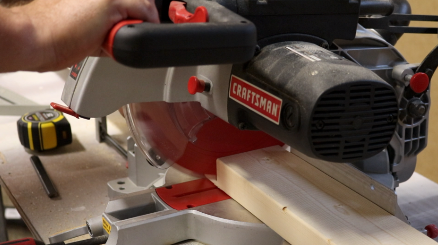
Miter saw action shot
The 2x6s are used to make the leg assemblies. I went ahead and ripped off 1 1/2″ from four of the pieces so the legs would be symmetrical. For those of you that aren’t obsessive compulsive this step is totally optional.
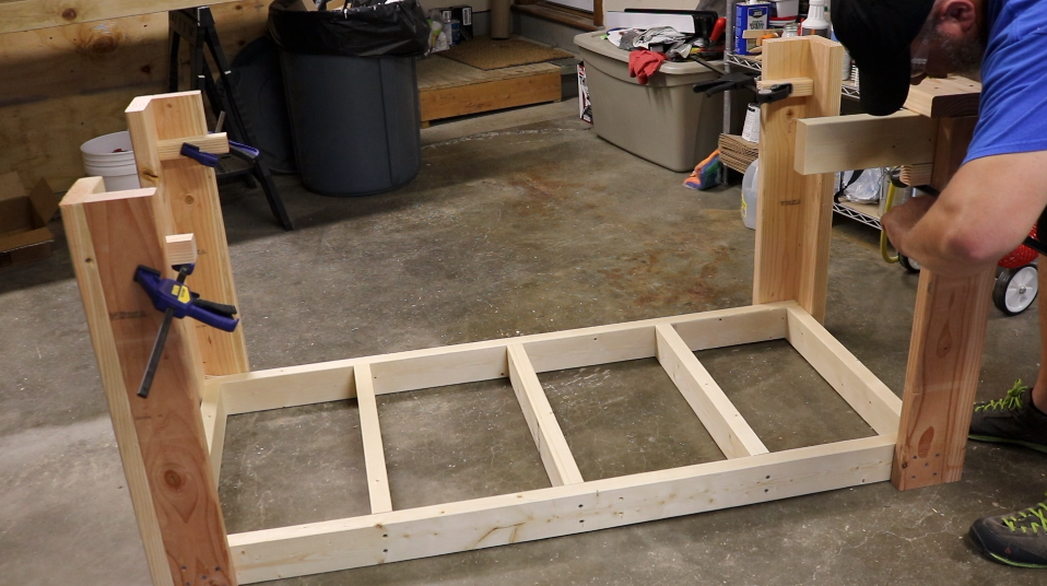
Assembling the Frame of the Assembly Outfeed Table
After we have all of the frame and leg pieces cut to size we can start screwing it all together. I started out by screwing together the perimeter pieces of the top and bottom parts of the frame. All parts of the frame were pre drilled and fastened together using 3″ deck screws.
Once you get the perimeters put together you can move them to the floor for easy fastening of the interior supports of the frame.
Assembling the Legs of the Assembly Outfeed Table
After the frames I moved onto the legs. Use pieces from the other legs to help hold things square. As with the frames I used 3″ deck screws to assemble the legs.
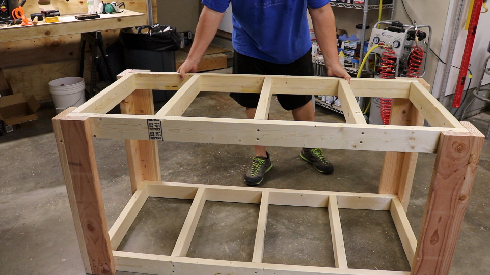
Attaching to the Frames
Once all of the legs are assembled, take one of the frames and attach the four legs to the frame again pre drilling and using 3″ screws while making sure to keep the end of the leg flush with the frame.
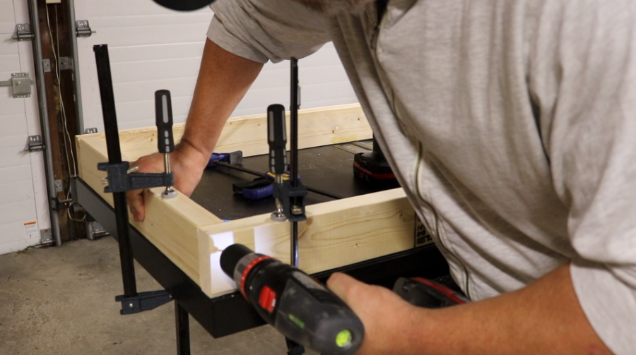
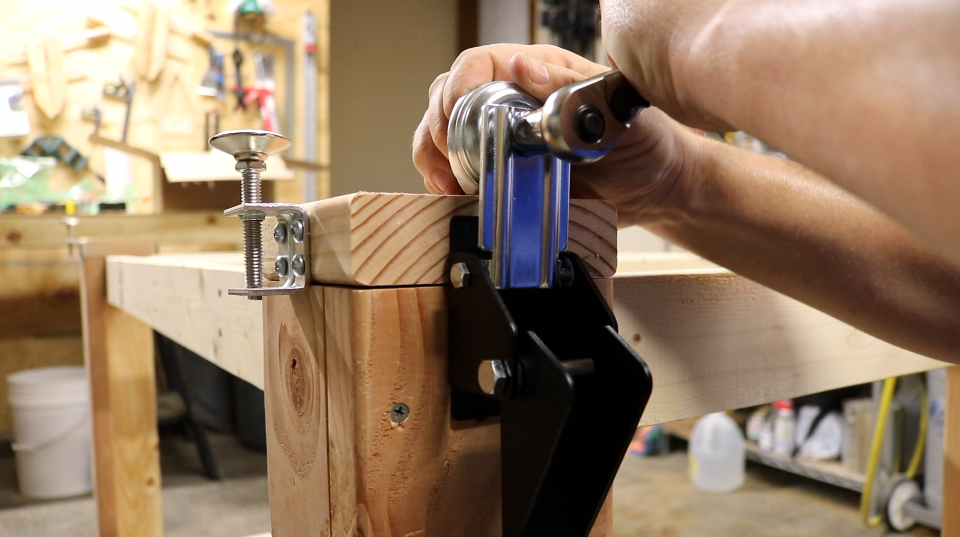
If you have a large, flat surface you can just flip the frame and leg assembly over and attach the other frame to the legs. The only large surface I have in my shop is my floor and, like Kansas, while it appears flat, on closer inspection there is quite a bit of undulation so I used a trick I learned from one of Jay Bates’ videos. Using a 2×4 as a spacer I clamped a block in place on all four legs. This allowed me to slip the frame inside the legs and easily align everything.
Use some scraps and clamps to accurately align the frame with the legs.
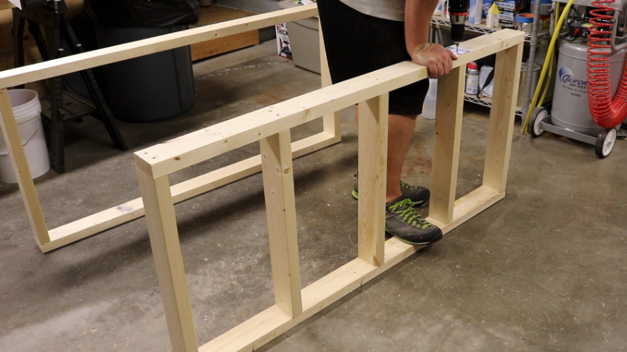
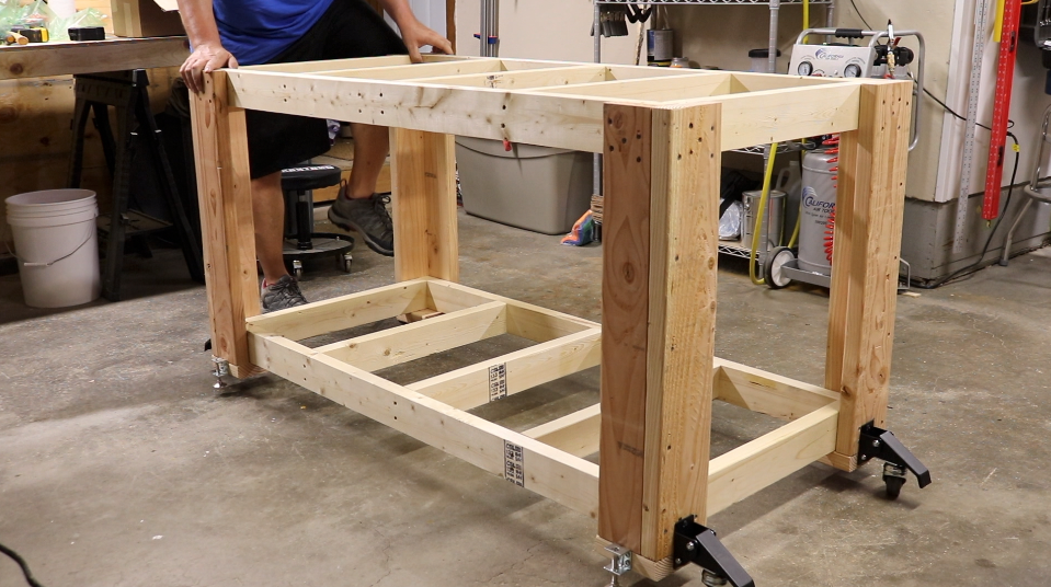
Huzzah, the frame and legs are assembled.
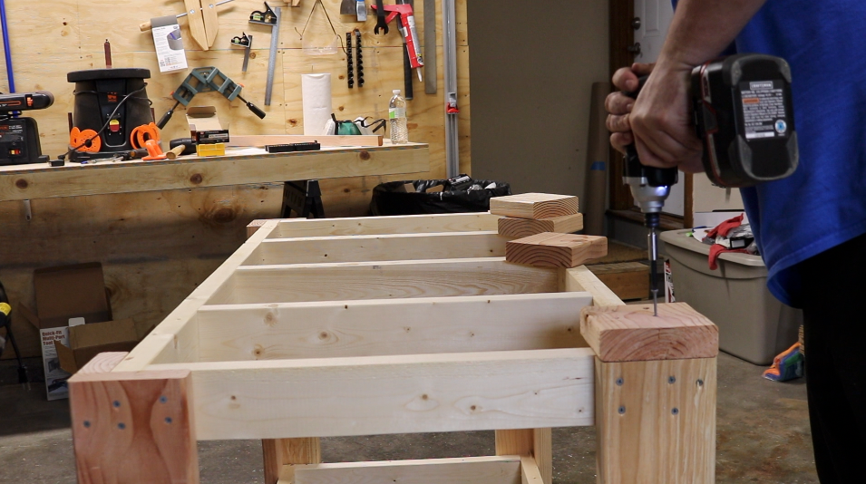
Cue the Mistakes
And now comes my once a project (if I’m lucky) brain fart. When I was brainstorming a design for the table I wondered how high I would need to have the extension so it would clear the back rail on my saw. I wrote that measurement down and a couple of days later put it to use in SketchUp. Unfortunately, I thought I had measured from the floor to the top of the table when in reality I had measured from the floor to the rail so the measurement was off by 1 1/2 inches. Off cuts from the legs proved useful as I just cut 5 1/2″ x 5 1/2″ pieces to attach to the bottom of the legs. The plans I made for this project correct this mistake so you shouldn’t need to do this step.
Giving the Assembly Outfeed Table Some Feet
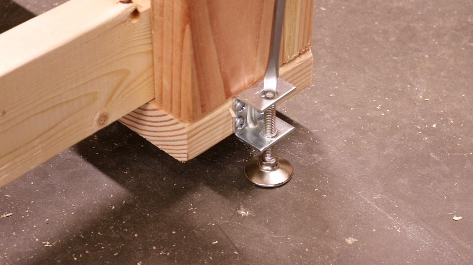
Once the frame was fully assembled it was time to attach the levelers. I centered the levelers and aligned the bottom of them flush with the bottom of the legs and then attached them with #10 x 3/4″ sheet metal screws.
I love these levelers. While some can be a pain to adjust these are not as they are adjustable from the top with a flat head screwdriver.
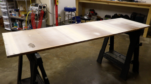
Starting on the Surface of the Assembly Outfeed Table
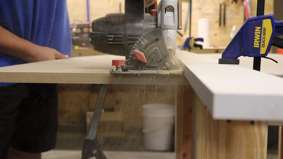
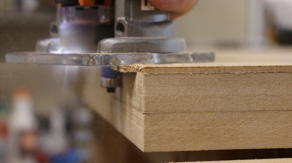
Time to move on to the top. I laminated two layers of 3/4″ MDF to create the top. I broke down the MDF sheets with my circular saw and table saw and made the the bottom layer a 1/4 to 1/2″ bigger than the top layer so I could go back with a my router and flush trim bit to ensure that the edges matched perfectly. If you’re going for the foldable extension option you are going to end up with four total pieces that make up the top.
Have a lot of glue on hand because laminating this top will take quite a bit. I spread the glue liberally on the bottom layers of the top and then put the top layer on. I used a few brad nails to hold the pieces in place while I clamped them down.
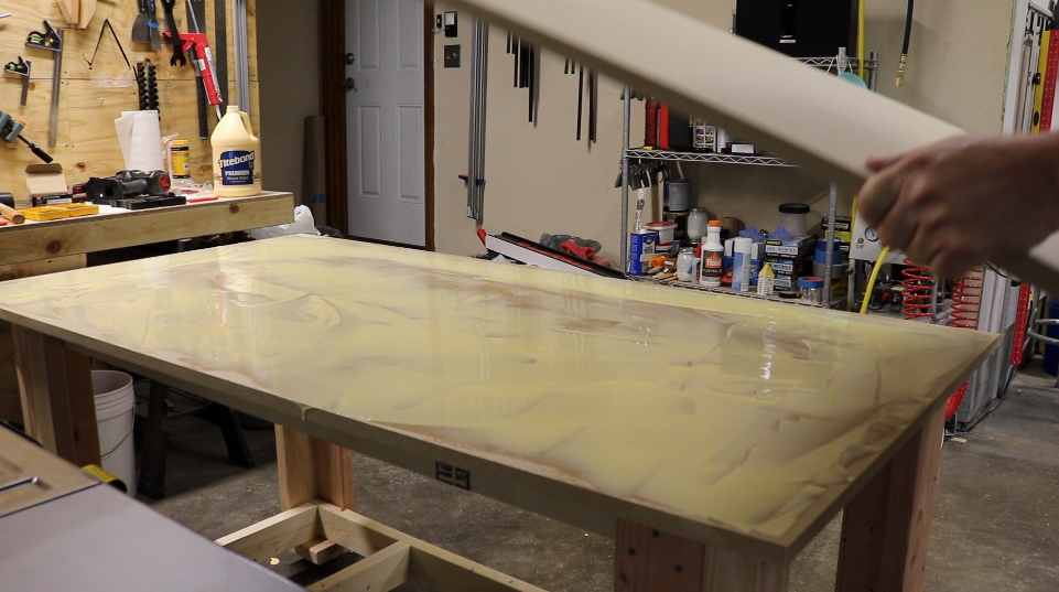
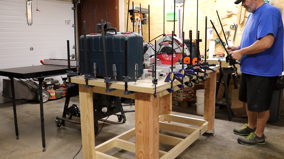
Since I couldn’t reach the middle of the top with clamps I grabbed the heaviest stuff I had in my shop to weigh it down. I then used just about every clamp I own to go around the perimeter.
Making it Mobile
With the top on the frame I positioned it against the table saw and leveled the table so I could then install the lifting casters. It’s important to do this step or you might get your levelers and casters spaced too far apart and the casters won’t lift the table. The installation of the casters was easy. I followed the directions on spacing and then used the two supplied screws to attach each caster. After that I bolted on the swivel wheels.
Thought a little expensive, I really like these casters. They are great for keeping heavy items like workbenches and assembly tables mobile.
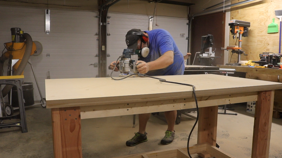
Making a Mess
Now that the table glue up has dried we can flush up the layers. I really wish I had done this step outside as I don’t have dust collection on my router. You can see the giant mess on the floor. It wasn’t contained to the floor. There was a think layer of MDF dust on everything in the shop! This was my first time working with MDF so, lesson learned.
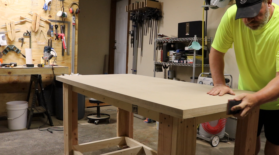
After flushing trimming I quickly hit the ends of the top with 120 grit sandpaper.
Adding the Fold Down Extension
Next, it was time to attach the extension to the main top. A piano hinge was used for this but there are various hinge options out there that can be used. I wanted a really tight seam between the top and the extension and started out by routing a slot for the hinge to sit in on each part of the top. I had some trouble getting things to align correctly and decided to just attach the hinge to the bottom of each piece. The screws that came with the hinge were pretty small (#4 x 1/2″ if I remember correctly). Since this hinge wasn’t going to be seen I decided to just use #8 x 1 1/4″ drywall screws. Be sure to drill pilot holes into the MDF.
Attaching the Top to the Base
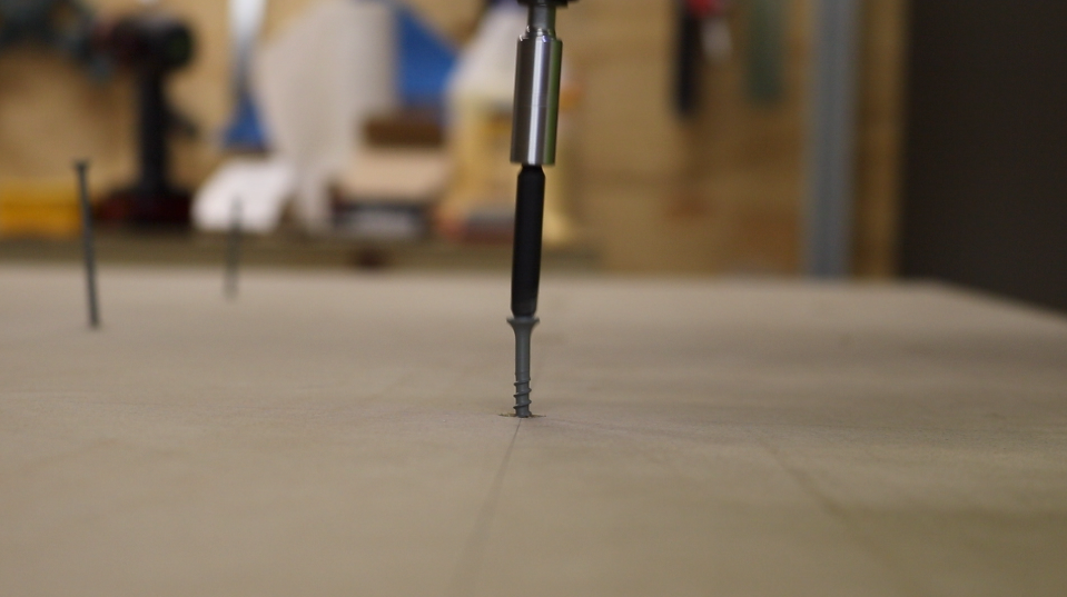
Now that the top is assembled we can fasten it to the frame. I centered the main part of the top on the frame, drilled pilot holes, and drove deck screws to secure the top. Note: you want to make your screws aren’t in the path of the miter slots we need to route out later in the project. I drove four screws per frame member.
Making the Extension Supports
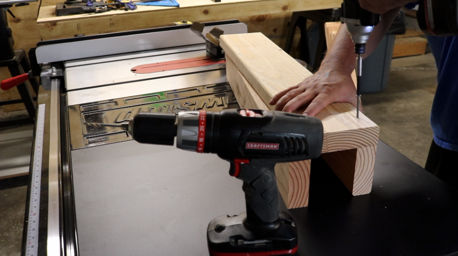
With the top in place I turned my attention to the supports and support brackets. Since I planned on trimming out the top with maple I decided to use maple for the brackets and supports as well, however, you could use any solid wood or plywood. I bought dimensioned maple from my local home center so the boards were 3 1/2″ wide which is the width I wanted for the brackets. Since the boards were already the width I wanted I figured I would just cut them into 1 1/2″ parts. This was mistake #2.
However, I file this under a lack of experience. The way I cut the parts meant I was going to be driving screws into the end grain. I would have been much better off cutting these so the screws would be into the edge grain as they have better screw holding power. These parts were pretty small which made them pretty brittle and I broke one of the brackets as I was driving a screw. Edge grain holds screws much better and this would have prevented my problem.
Cutting the Support Parts to Size
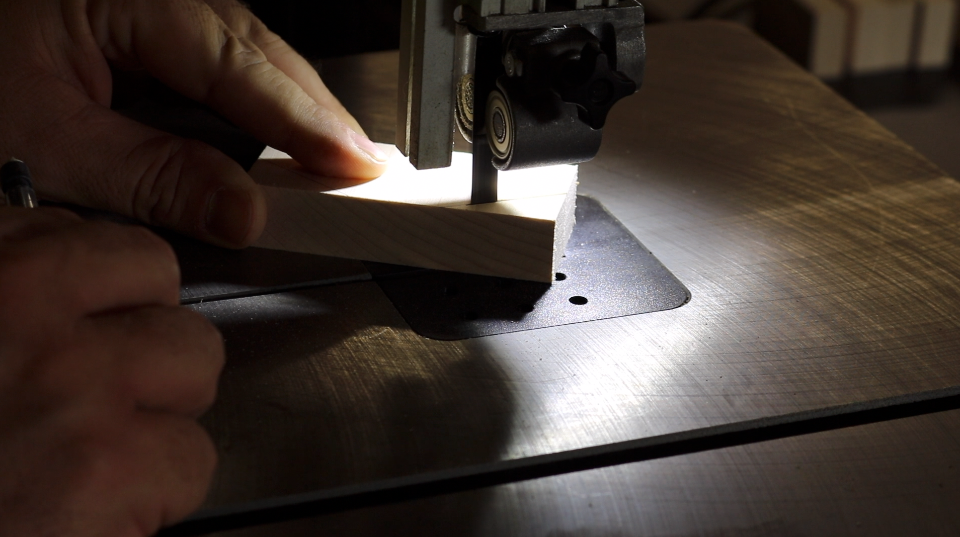
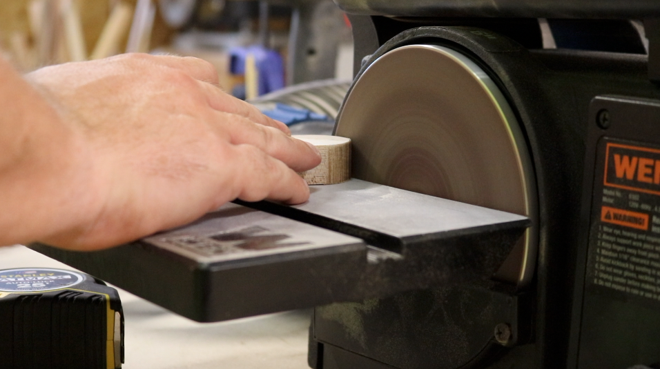
Once all the bracket parts were cut I took them over to the bandsaw to pretty them up a bit by angling two of the corners.
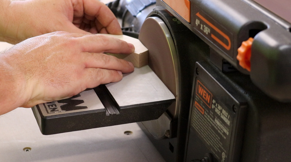
I then hit them with the disc sander to smooth out those cuts.
Machining the Support Parts for the Assembly Outfeed Table
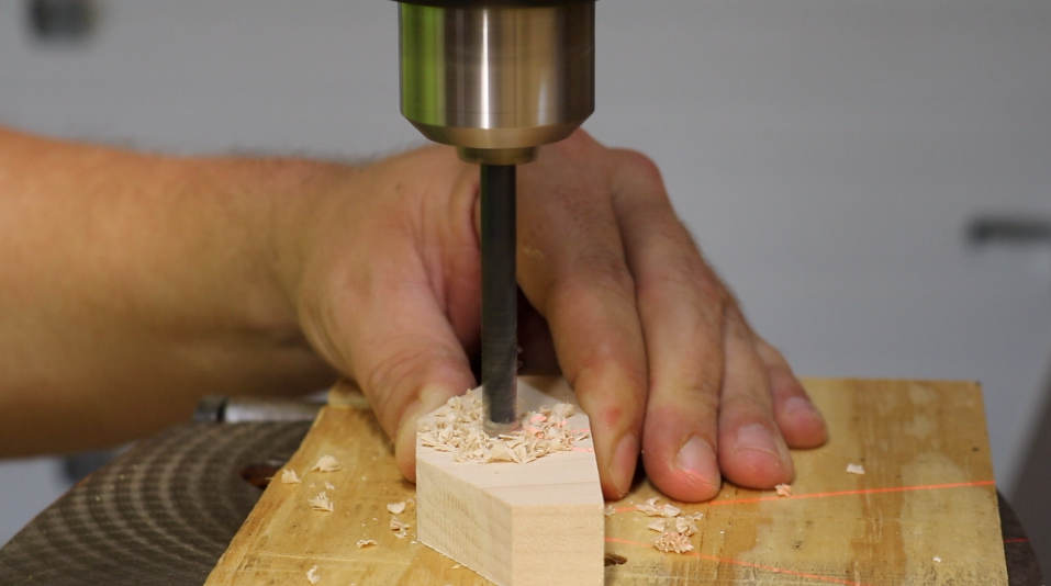
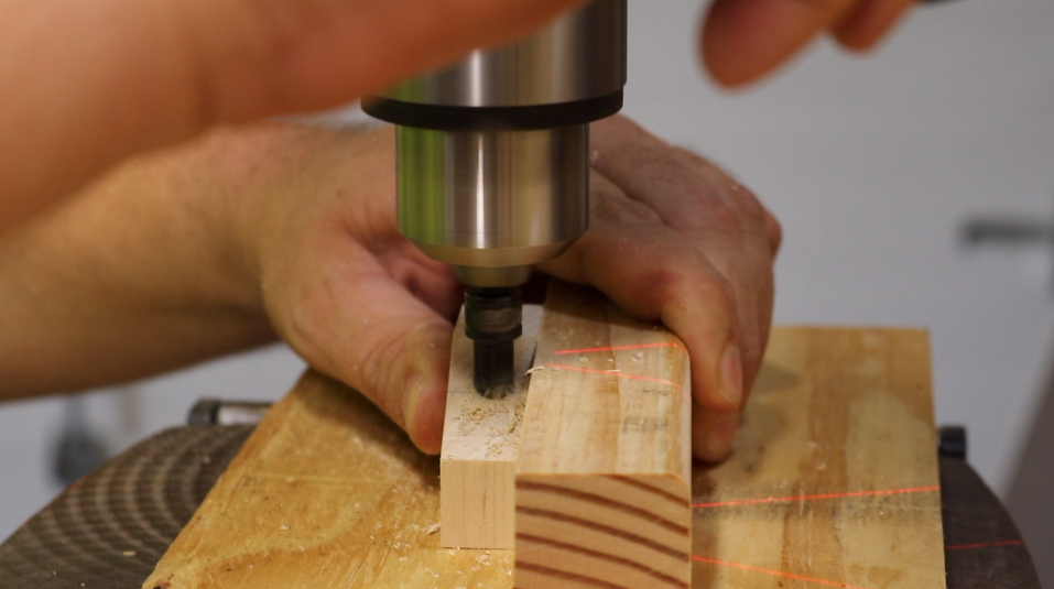
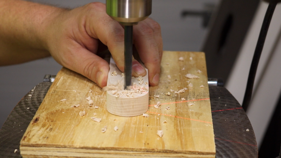
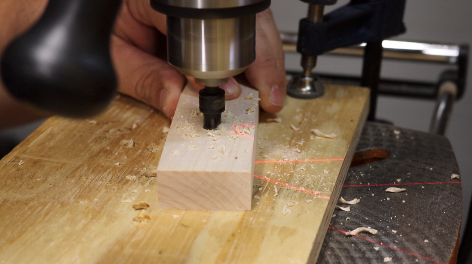
Over at the drill press I drilled out the holes for the support bolts and the screws to attach the brackets to the legs.
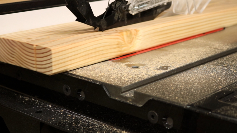
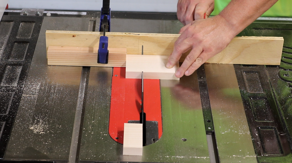
I used the same maple to make the supports, first ripping them down at the table saw and then rounding the corners over at the bandsaw. My bandsaw isn’t great which meant quite a bit of time at the disc sander to get the corners nice and smooth and symmetrical.
Ripping the supports
Sanding down the corners on the supports
Headed back to the drill press again and made the holes for the support bolts.
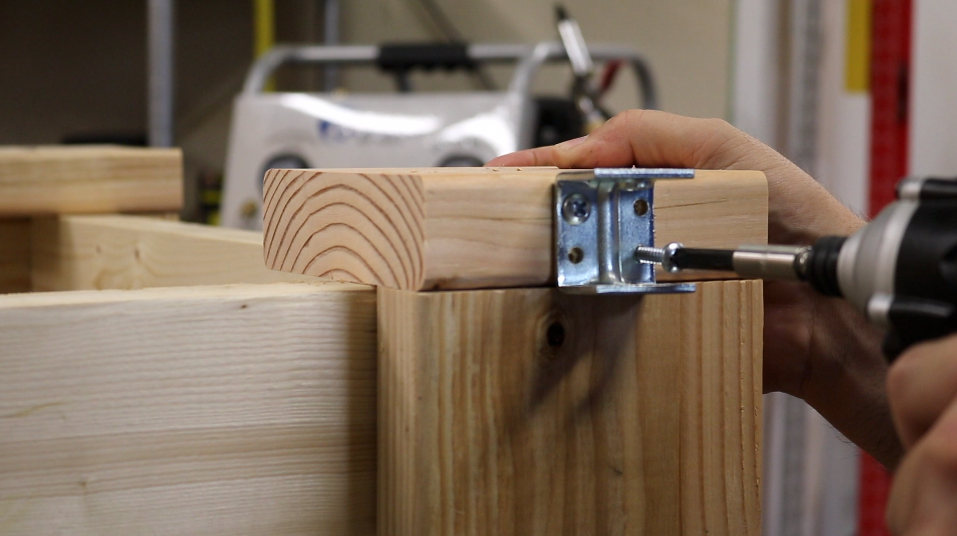
Assembling and Attaching the Extension Supports
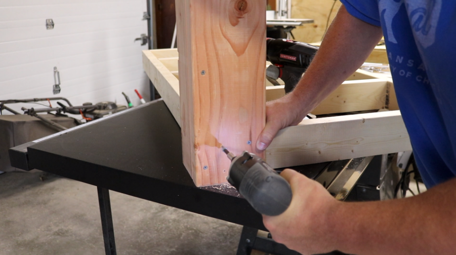
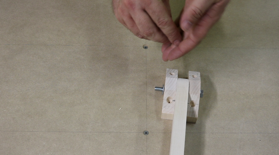
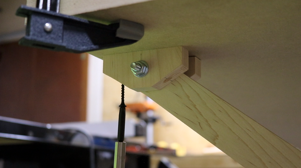
Now that all of the support parts have been cut I can attach them to the top and legs. This was most easily done by assembling each support and then using some cauls to hold the top and extension in line with each other. I then played around with the positioning of the support assembly and once I was satisfied I drilled pilot holes into the legs.
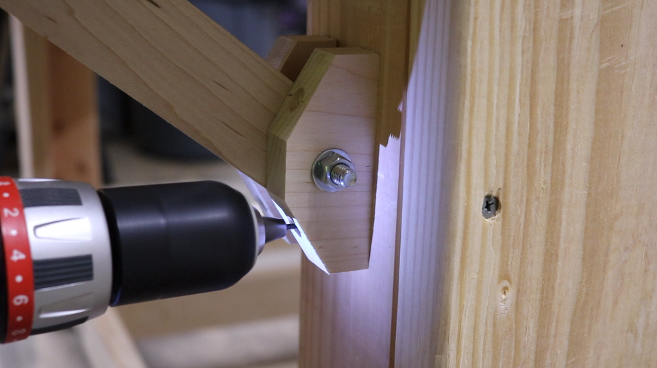
I used #8 x 1 1/2″ screws to attach the supports to the legs. If you’re using hardwood for the supports then your pilot holes need to be a little bigger. Here’s a chart that shows the difference in pilot hole sizes between hardwood and softwood: chart.
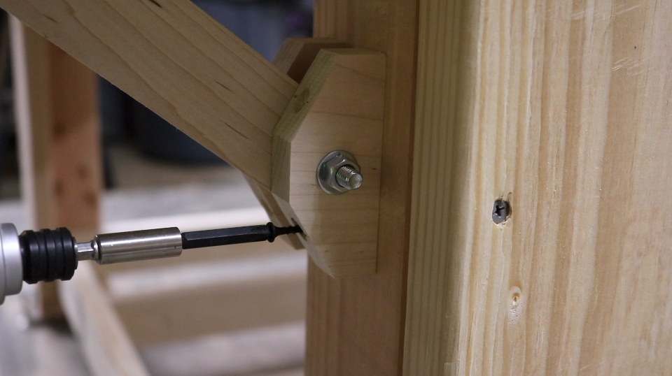
I was then able to get the support assembly snug to the top and attach it in a similar fashion.
Make the Top of the Assembly Outfeed Table Replaceable
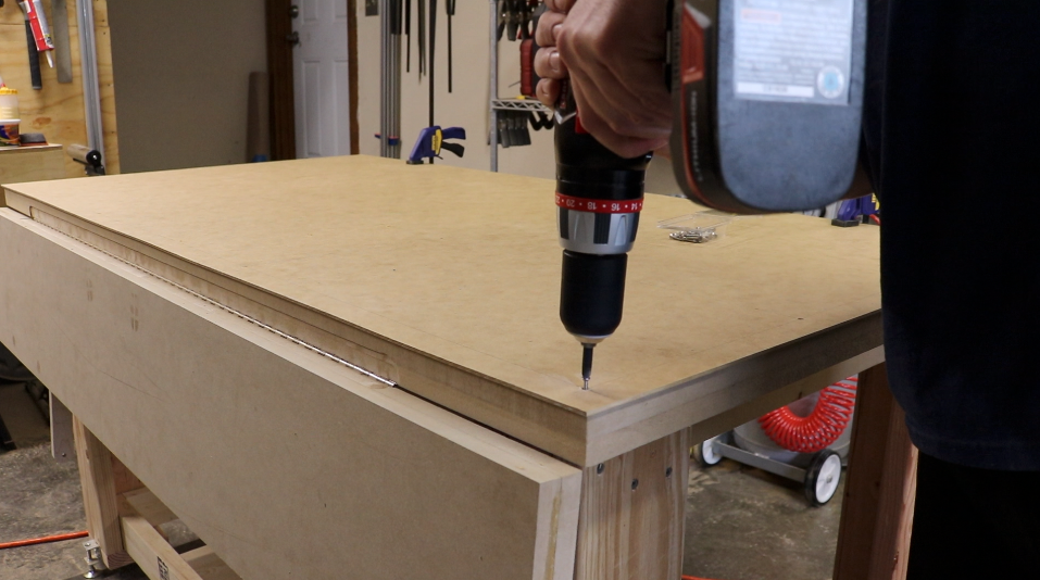
With the extension in place I moved on to adding the hardboard top. I am adding the hardboard top based on Marc Spagnuolo’s assembly table design. The idea here is that you can easily replace the hardboard as the top gets beat up. I cut the hardboard pieces about 1/4″ bigger than the tops so I could use the flush trim bit again to make everything nice and flush. I pre-drilled some countersunk pilot holes in a pattern similar to how we attached the top to the frame, then fastened the hardboard to the MDF with #6 x 3/4″ sheet metal screws. Again, make sure you don’t put screws where you’ll be routing out the miter slots.
Flushing up the hardboard top
Adding Some Finishing Touches to the Assembly Outfeed Table
I ripped down 1 5/8″ (3/4″ + 3/4″ + 1/8″ = 1 5/8″) pieces of maple to be used for the table trim.
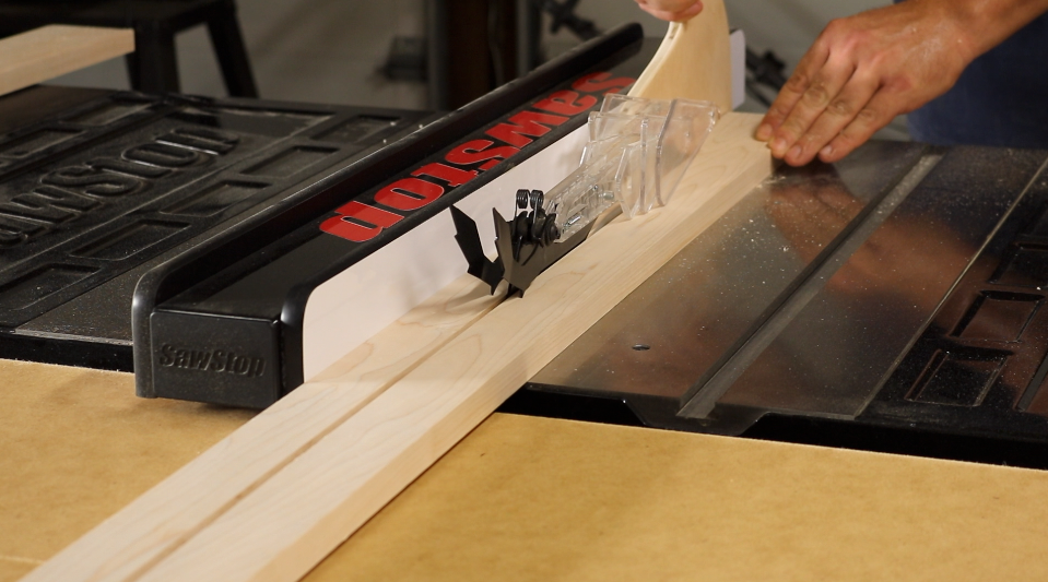
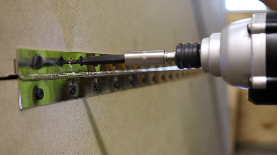
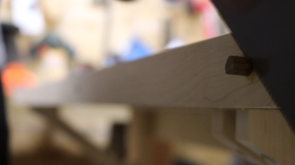
Then I filled the wholes with walnut dowels. I made the countersinks to allow for about a quarter inch of dowel. Like the brackets, I made the pilot holes in the maple bigger than the pilot holes in the top.
Using a caul made aligning the trim pieces flush with the top very easy. I applied some glue to each trim piece and then fastened with 1 1/2″ screws.

After gluing in the dowels I cut them to size with a flush trim saw.
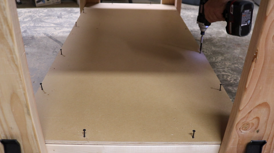
Let’s Add a Shelf to the Assembly Outfeed Table
A scrap piece of 1/2″ MDO plywood made for a good option for the bottom shelf which I attached to the bottom frame with 1 1/4″ screws.
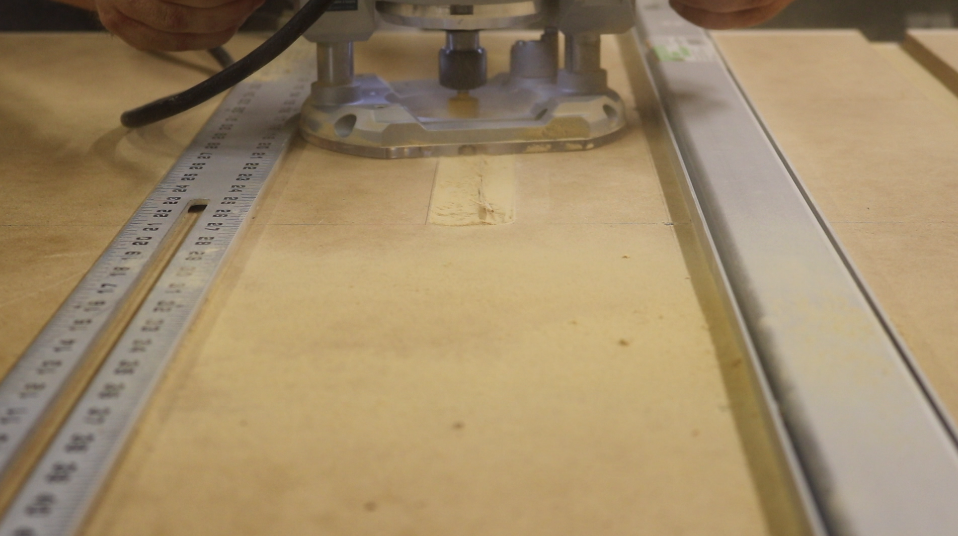
Gotta Make Room for the Miter Gauge in the Assembly Outfeed Table
Using a router with a straight bit and a couple of straight edges made quick work of the miter slots. I made these about 1″ wide and a half inch deep. I really wish I had some sort of dust collection on my router. This makes such a mess. I made the cuts in a couple or three passes. After cutting the miter slots the hardboard top was a little flimsy in a couple places so I went back and added in a few more screws.
A Quick Sanding of the Assembly Outfeed Table Trim
After I cut the miter slots, I just needed to sand down the trim.
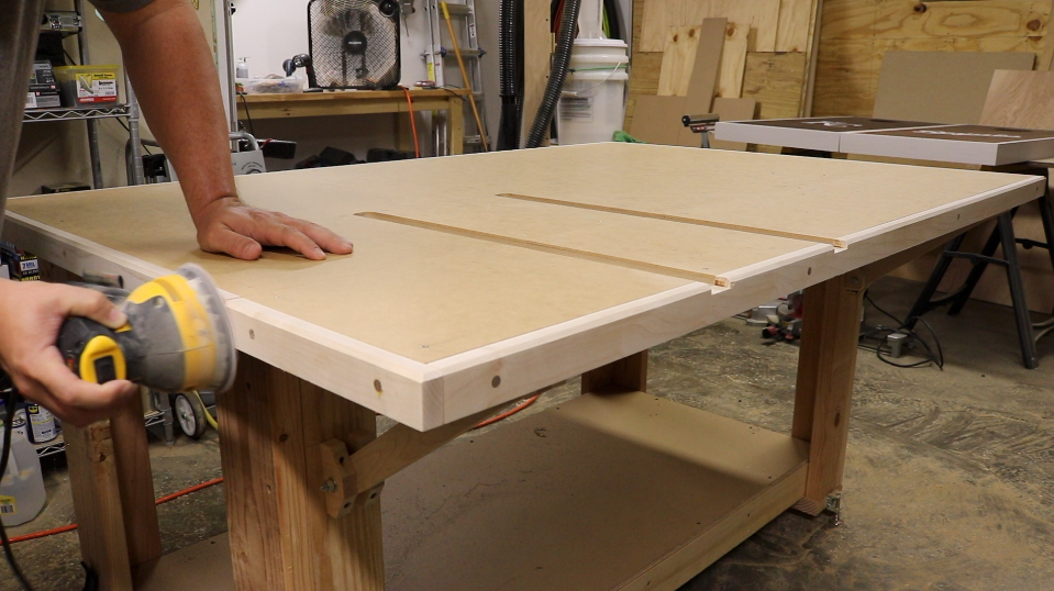
Aaaaaaand done!
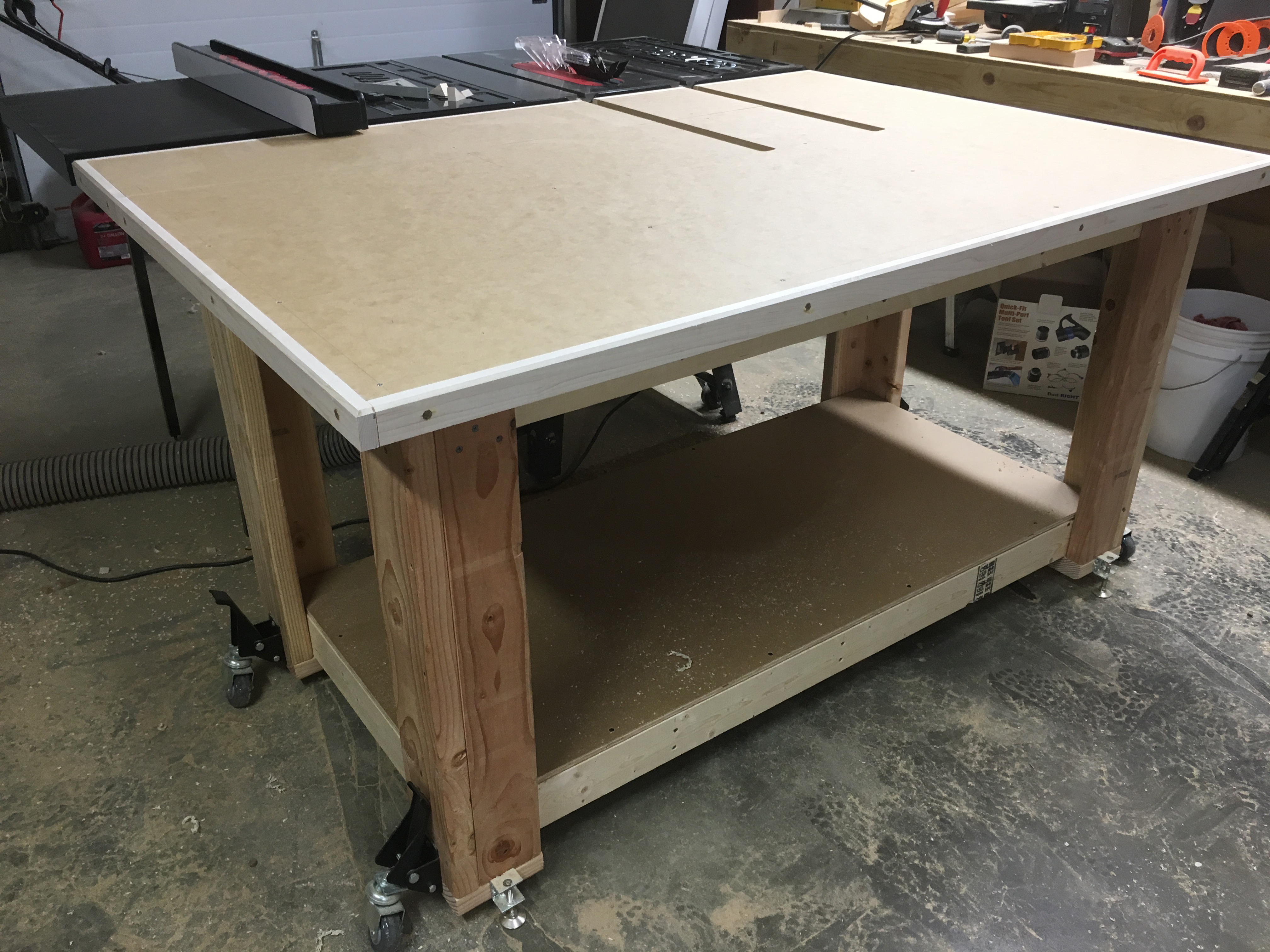
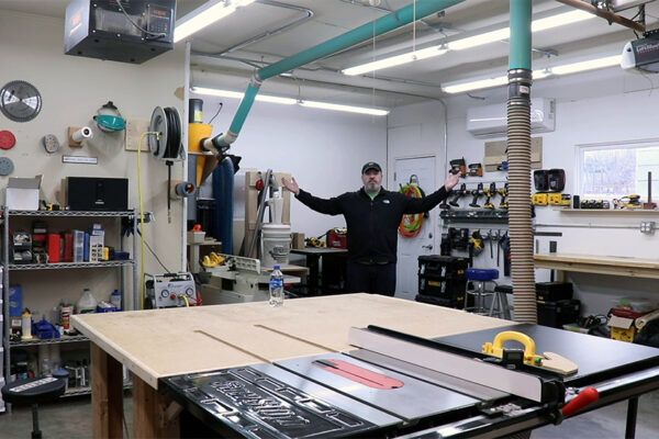
That’s a Wrap
So far, I love the table. It’s been one of the best additions to the shop to date. It solved two big issues and made the shop much more organized. I will update you after using it for a few months to see if it delivers what I hope.
Overall, the build was pretty simple. I probably made it a little more complicated that it needed to be with the fold down extension but it was a chance to do a few things I hadn’t done before. One of the great things about shop projects is that often times they provide you the opportunity to hone or tackle new skills.
Not only did I find this a great shop project, but I also documented a project for the first time. Adding a camera to the shop and my workflow was challenging but quite a bit of fun. I look forward to the next one!
If you’re interested in building this table I have a set of plans available: Assembly/Outfeed Table Plans.
I would love to hear from all of you regarding the project, the plans, the video, or anything related to this project or site so by all means please leave a comment below. Positive or negative, all feedback is welcome.
2 Comments
[…] Assembly/Outfeed Table – The Average Craftsman […]
[…] Assembly/Outfeed Table – The Average Craftsman […]